Making a Jockey Shift
Making A Motor Mount Jockey Shifter
By bungking
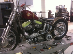
In this post I am going to show you how I make a tank style Jockey Shifter with an integral motor mount on one of our panhead projects using some of our parts that come off the shelf as well as some custom made ones. Pictured above is the rigid panhead I am starting with.
This is one of our off the shelf jockey shift motor mount kits fromwww.bungking.com they are available in all common Harley motor types from pans to twin cams. The kit comes with all of the machined parts you will need to make the motor mount and pivot, you will need to add your handle and shift rod of your choice. The kit comes with the counterbore bungs that mount to the heads, a center bung with integral pivot which includes a bronze oilite bushing for long life a stainless shoulder bolt so you can tighten the bolt completely without binding up the free movement of the pivot and extra long round bar that can be trimmed to length.
This shows the couterbore bungs in place on the heads and the center bung mounted in place on the chassis tab in the center of the motor. If you are making a motor mount for a pan or shovel make sure that the heads are bolted in place and clocked correctly to match up with the intake manifold.
Next cut the supplied round bar to the correct length to span the gap between the two bungs. After cut to length I tack them in place.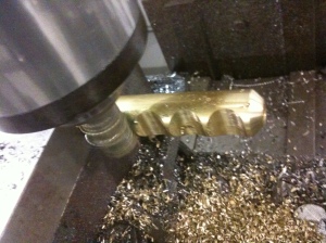
After the bulk of the motor mount was made I moved my attention to the jockey shift section of the piece. First I made up a custom brass handle. The customer requested a brass handle but wanted somewhat of a knife or pistol grip style handle and this is what I came up with on the fly. Taking a piece of solid round brass and cutting four round reliefs in it to form the finger grooves on the mill.
Next I made up the upper and lower bars that would be located above and below the pivot of the motor mount, these were drilled and also milled a small slot in them for a little more texture and interest to the simple round bar.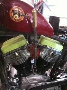
Once all of the machining is done it is time to tack the parts to the pivot assembly, I also added one of our threaded bullets to the bottom of the shift arm for attachment of the shifter linkage.
I then measure the travel in straight line distance that the assembly has with proper clearance to all the parts around it in this case the tank and the cylinders. In this assembly I have approximately 3 3/4″ of travel.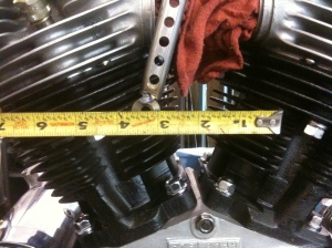
After I find out how much travel I have the ability to use I can then make some layout lines on the shifter arm that is attached to the transmission. In the same fashion I will measure the travel needed at different points vertically to find a point on the arm that needs slightly less travel than the 3 3/4″ distance that is available from the other arm. I found a point that needed about 3 1/4″ of travel to complete both an up and down shift and marked its location.
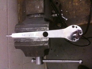
I am going to be using a purchased arm to save some time they are relatively inexpensive and the 5 holes drilled for mounting on a 4 speed have to be very precise. I straightened the bends that this arm had in them and located the point at which I found earlier and drilled the center of the hole out to a 3/4″. I am going to be welding another one of our threaded bullets for the rear location of the shifter linkage. By drilling the hole before cutting the arm down to length you can achieve a tight gap free fit for the 3/4″ dia bung much faster than cutting the arm down and trying to cope it after.
This is the cut down arm with the bullet tacked into place and attached back on to the shift drum of the transmission. We stock these bullets atwww.bungking.com in variety of lengths and threaded pitches to fit your needs if you would like to see if we have the correct size for you check out tis link for sizing and pricing.
http://www.bungking.com/bungs-1/threaded-bullets.html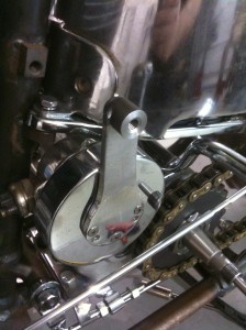
Next it’s time to measure the eye to eye length needed for the shift linkage to attach both of the arms together to complete the assembly. It is best to keep the ars as vertical as possible in their rest condition ( when in between the u and downshift location) this will give you the most positive forward and back movement without having a bunch of un wanted up and down movement that is caused by the arch that the two pivots will cause these two points to move in.
Next I made up a custom length shift linkage with our stainless heim joints in a 5/16 dia and some threaded 5/16 stainless rod threaded to the correct length. We can custom make these to you specific size if you need one of your own, the individual heims are available as well throughwww.bungking.com the link to the linkages ishttp://www.bungking.com/accessories/shifter-linkage.html
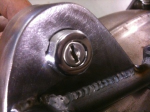
The customer wanted to add an ignition switch to the motor mount as well. I made up a sheet metal housing to hold the switch in place as well as cover it from view. Most ignition switches have a flat spot machined into the threads to keep them from rotating once installed in place. A trick you can use is to drill the hole to the proper hole size and then place a small tach on the edge of the hole in one location where needed.
I then finish sand the tach down and fit the key switch in place and this gives a key way in the hole to keep any rotation of the ignition switch down to a minimum.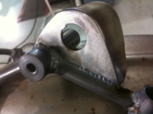
I then disassemble the mount and fully weld all of the parts and reinstall to check and make sure all of the fitment is good before the parts are shipped off to the chromer.
Explore Popular Articles
Nate’s Shovel
September 10, 2011Nate’s ShovelBy bungkingThis bike was built completely from scratch using all new...
Gary's CFL
September 10, 2011Gary’s CFLBy bungkingThis started as a standard CFL chassis. I dropped the neck do...
JD's Shovel
September 10, 2011Jd’s ShovelBy bungkingThis Bike started it’s life as a stock swingarm frame FL, We...

